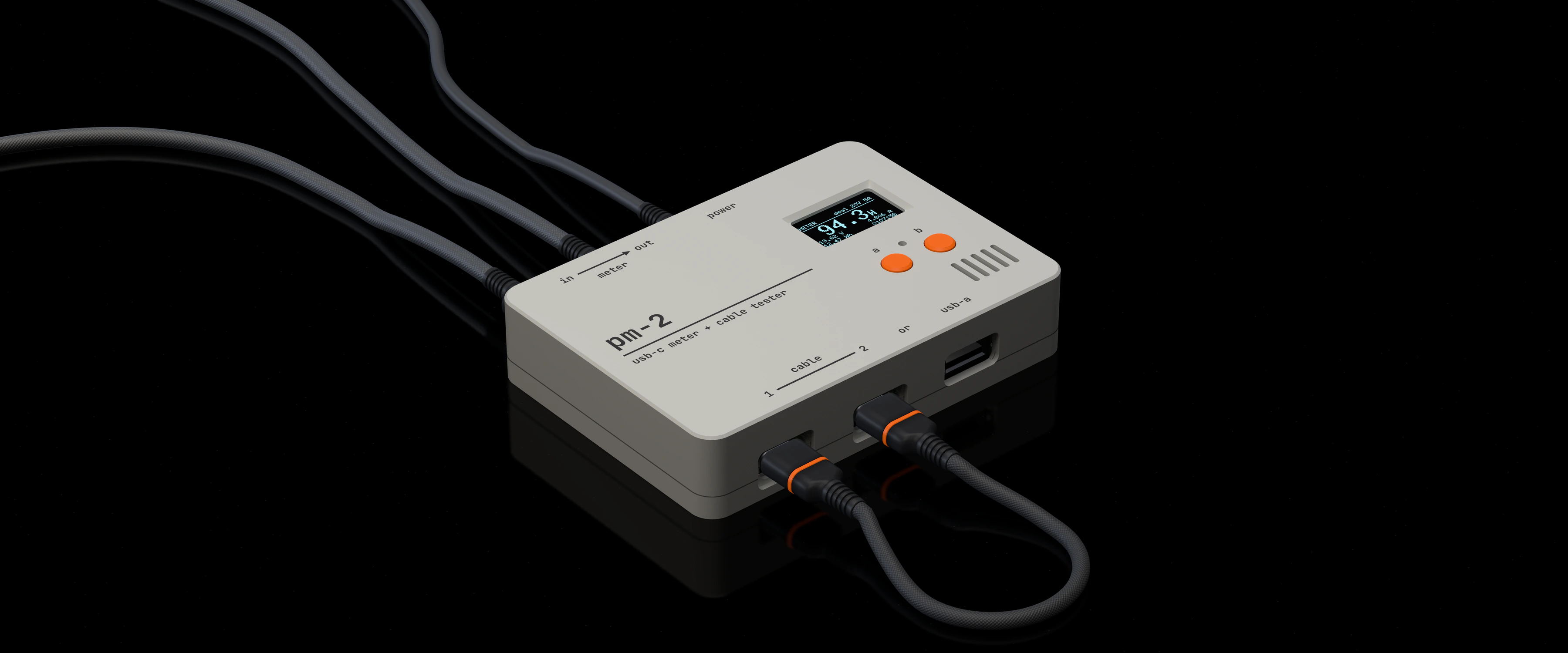
PM-2 on a black studio floor: a small light-grey box lettered pm-2, with four braided cables plugged into five of its sockets, two orange buttons and a small display reading 94.3 W.

A small desk box
that tells you
three things about
USB-C charging.

PM-2 picks the mode from what is plugged in.

status
PM-2 is a design. Nothing has been built, tested or measured, and the readings on this page are the example numbers from the display mock-ups.
made
As a personal project. It is not for sale.

01 / meter

charger into in · device into out

How much power is really flowing.

PM-2 sits between a charger and a device. The display shows volts, amps, watts, energy, and the deal the two agreed.
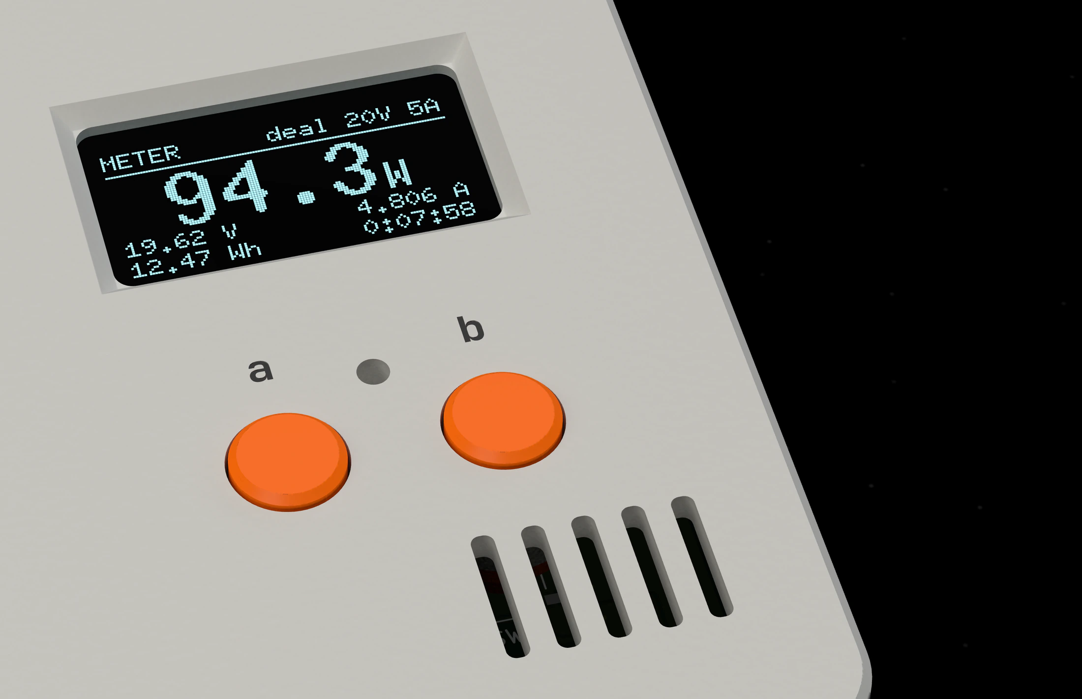
The display, close up, behind black glass in the light-grey lid. It reads METER, deal 20V 5A, 94.3 W, 19.62 V, 4.806 A, 12.47 Wh, 0:07:58. Below it are two orange buttons lettered a and b, and five vent slots.
fig. 1The meter page, close up. 128 × 64 pixels behind black glass, above the two buttons.

94.3W

= 19.62 V × 4.806 A

02 / cable test

one cable, both ends in: 1 and 2, or 1 and usb-a

Whether a cable is any good.

Put both ends of one cable into the box. PM-2 checks the 24 contacts in each USB-C test socket, measures the resistance of the power and ground wires, reads the cable's chip if it has one, and gives a verdict.
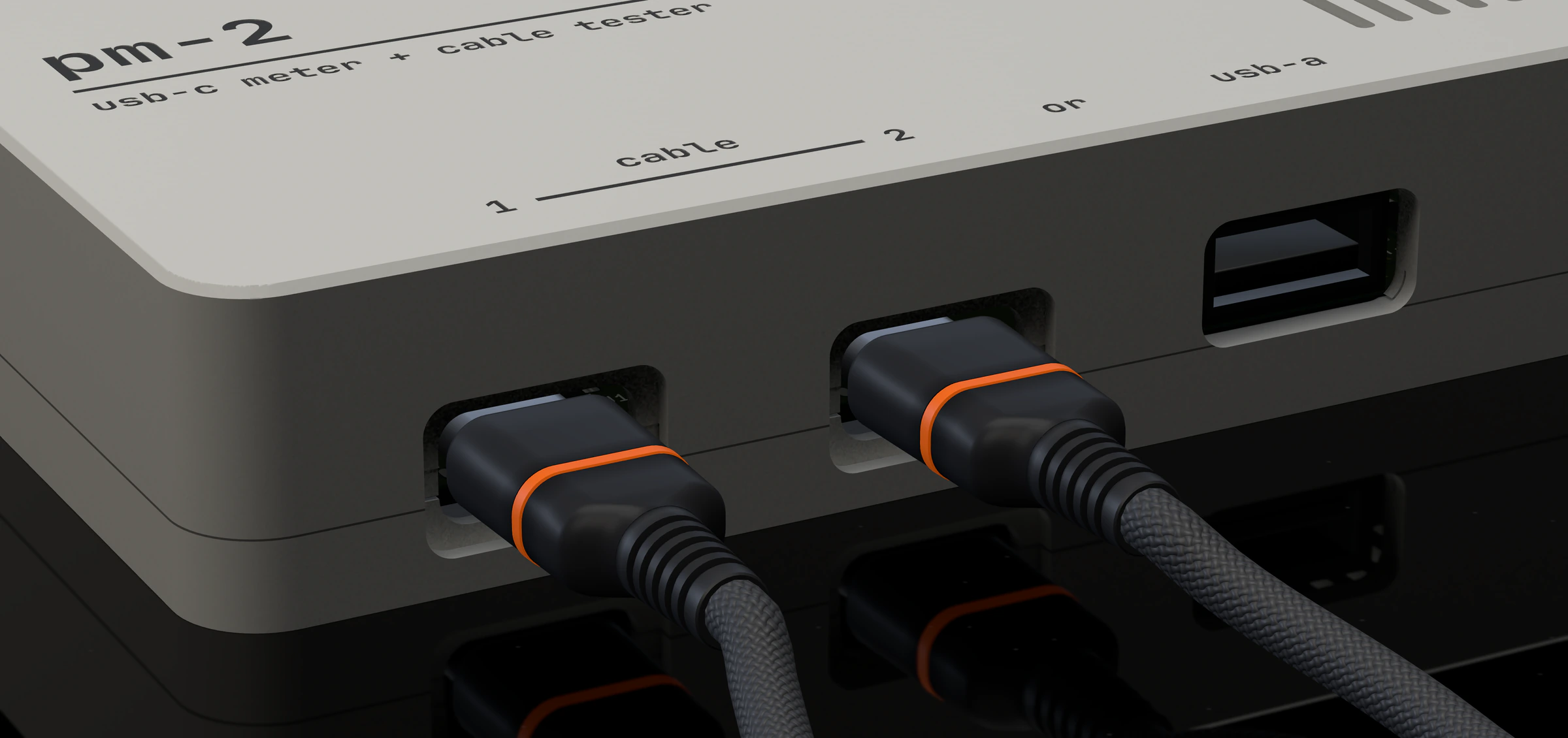
The near edge of the box, low and close. Two USB-C plugs with orange rings sit in the sockets lettered 1 and 2, joined by one braided cable. The usb-a socket beside them is empty.
fig. 2The near edge. A cable test is one cable with both ends in: here, 1 and 2.

GOODdisplay page 07

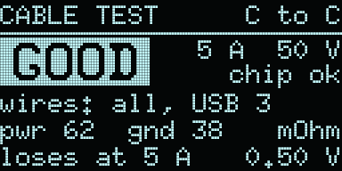
Display page: CABLE TEST, C to C. GOOD. 5 A, 50 V, chip ok. Wires: all, USB 3. Power 62, ground 38 milliohms. Loses at 5 A: 0.50 V.

0.50V

lost at 5 A

power wire
62 mΩ
ground wire
38 mΩ
wires
all, USB 3

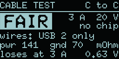
FAIRdisplay page 08

Display page: CABLE TEST, C to C. FAIR. 3 A, 20 V, no chip. Wires: USB 2 only. Power 141, ground 70 milliohms. Loses at 3 A: 0.63 V.

0.63V

lost at 3 A

power wire
141 mΩ
ground wire
70 mΩ
wires
USB 2 only

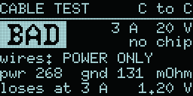
BADdisplay page 09

Display page: CABLE TEST, C to C. BAD. 3 A, 20 V, no chip. Wires: power only. Power 268, ground 131 milliohms. Loses at 3 A: 1.20 V.

1.20V

lost at 3 A

power wire
268 mΩ
ground wire
131 mΩ
wires
power only

The loss is the two resistances times the current: (62 + 38) mΩ × 5 A = 0.50 V.
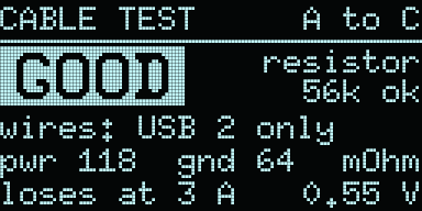
Display page: CABLE TEST, A to C. GOOD. Resistor: 56k ok. Wires: USB 2 only. Power 118, ground 64 milliohms. Loses at 3 A: 0.55 V.
A to Cdisplay page 11

A USB-A to USB-C cable goes into 1 and usb-a. PM-2 then checks one thing more, the cable's resistor. 56k is the right one.

03 / charger check

charger into in · out left empty

What a charger offers.

With a charger plugged in and nothing on the other side, the display lists what the charger offers through that cable, with no load.
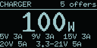
Display page: CHARGER, 5 offers. 100 W. 5V 3A, 9V 3A, 15V 3A, 20V 5A, 3.3 to 21V 5A.
chargerdisplay page 13

100W

five offers, the largest 100 W

04 / six sockets

five USB-C · one USB-A

Six sockets, on two edges.

The meter's sockets and power are on the far edge. The cable test has the near edge to itself. The display stays dark until a cable is in power.
The lid from above A rounded rectangle. On the far edge, at the top, three sockets lettered in, out and power; an arrow lettered meter runs from in to out. On the near edge, at the bottom, three sockets lettered 1, 2 and usb-a; a line lettered cable joins 1 and 2. The display window, two buttons lettered a and b, and five vent slots are on the right. The lid is lettered pm-2, usb-c meter + cable tester. pm-2 usb-c meter + cable tester in out power meter 1 2 cable or usb-a a b
fig. 3The lid from above, lettered as it is drawn. Far edge at the top.
in
USB-C
The charger side of the meter. Also the charger check.
out
USB-C
The device side of the meter.
power
USB-C
Powers the box. Connected in every mode.
1
USB-C
One end of every cable under test.
2
USB-C
The other end of a USB-C to USB-C cable.
usb-a
USB-A
The USB-A end of a USB-A to USB-C cable.
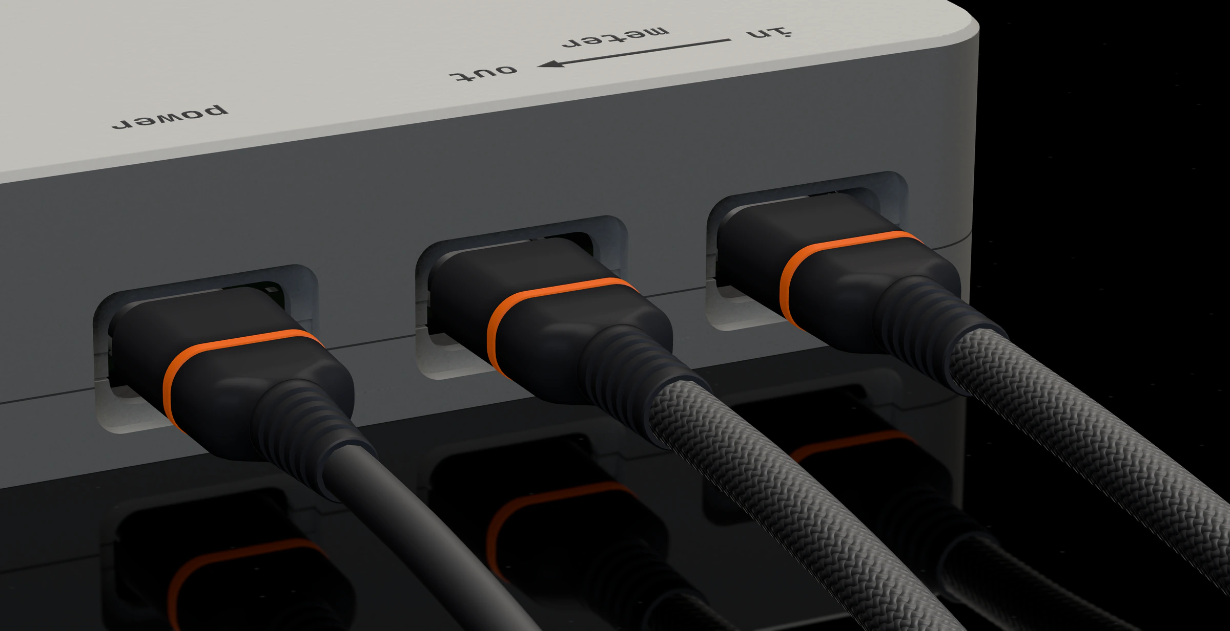
The far edge of the box, low and close, seen from behind. Three USB-C plugs with orange rings sit in the sockets lettered power, out and in; their braided cables run off across the black floor.
fig. 4The far edge, seen from behind. Left to right: power, out, in.

05 / in figures

ten numbers

The design, in figures.

volts, designed for up to
48V
amps, designed for up to
5A
shunt, between in and out
5mΩ
power monitors
4
board
100 × 70mm
display pixels, behind black glass
128 × 64
contacts checked in each USB-C test socket
24
copper layers
4
sockets
6
buttons
2
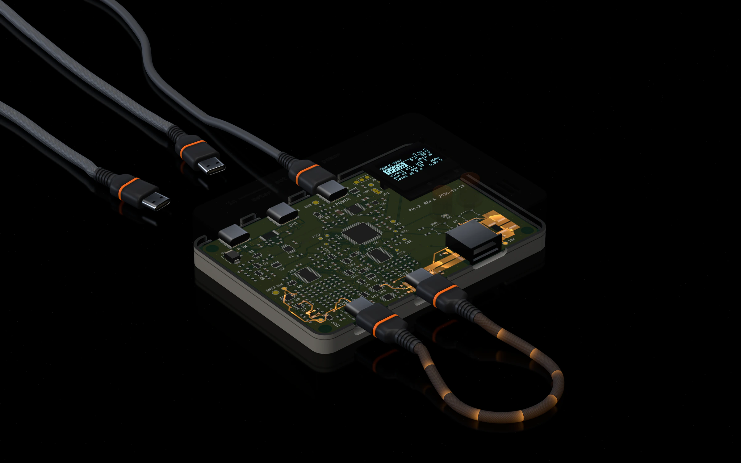
The box in x-ray: the lid has faded and the green circuit board shows inside the tray. Orange dashes mark the current running out of socket 1, round the looped cable and back in at socket 2. The display reads GOOD.
fig. 5X-ray, during a cable test. The current leaves 1, runs along the cable, comes back in at 2 and goes through the test load.

06 / the 3D page

pm-2, plugged in

Plug it in yourself.

The 3D page is a product photograph that moves. When it loads, an unseen hand tells the story once. Then the box is yours.
click
A socket or a plug. It goes in, or comes out.
drag
On the dark, to turn round the box. Scroll to come closer.
X
X-ray. The lid fades and the current runs along the copper.
E
Apart: lid, buttons, display, board, tray. Again to put it back.
1–5
The cable under test: good, fair or bad, then two USB-A to USB-C cables.
touch
Tap a socket or a plug, drag to turn, pinch to zoom, tap the display to read it. Buttons on the page do x-ray, apart and the next cable.
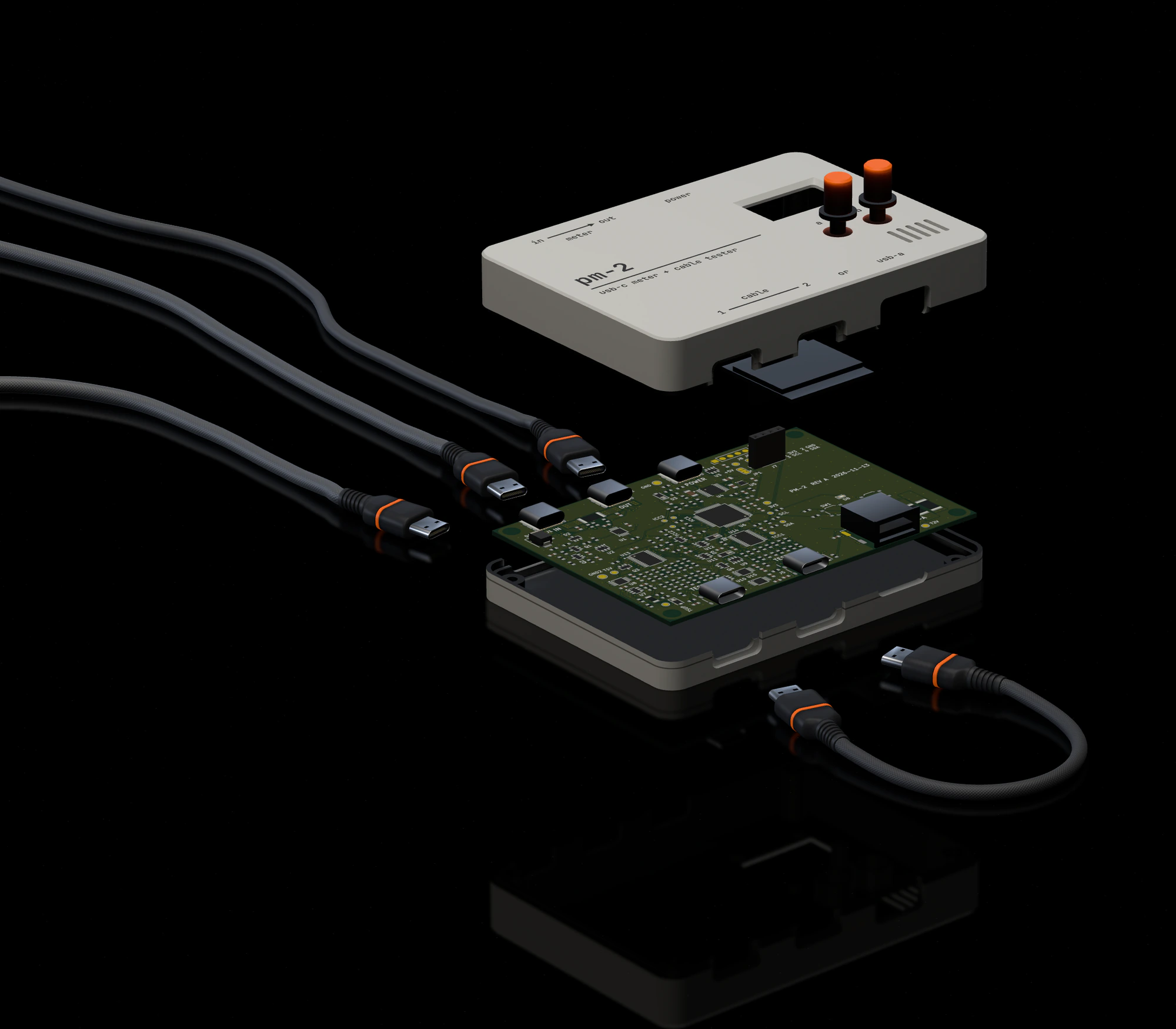
The box taken apart along one axis: the lid with its two orange buttons floats above the display, the green circuit board and the tray. The plugs lie pulled out on the black floor.
fig. 6Apart: lid and buttons, display, board, tray. The plugs come out first.

07 / how the page was made

in three lines

  1. The light is baked, from the Blender scene built for the film of the same box.
  2. The display is drawn by a port of the mock-up page code: the same 128 × 64 pixels.
  3. In the x-ray, the current is drawn along the board's real copper.